

test_rack: PSU and PDU

Disclaimer: This involves working with mains voltage. Do similar work only at your own risk. Avoid the mains voltage part unless you know what you are doing.
To power the testjigs, we need the power source - PSU, and a convenient way to connect the testjigs. I figured that 12V/16A power source should be enough for my needs.
In the rest of the article, I will show details of the PSU and PDU assembly. If you are interested in printing this, all the files are in the repository: https://github.com/emsro/test_rack
PSU
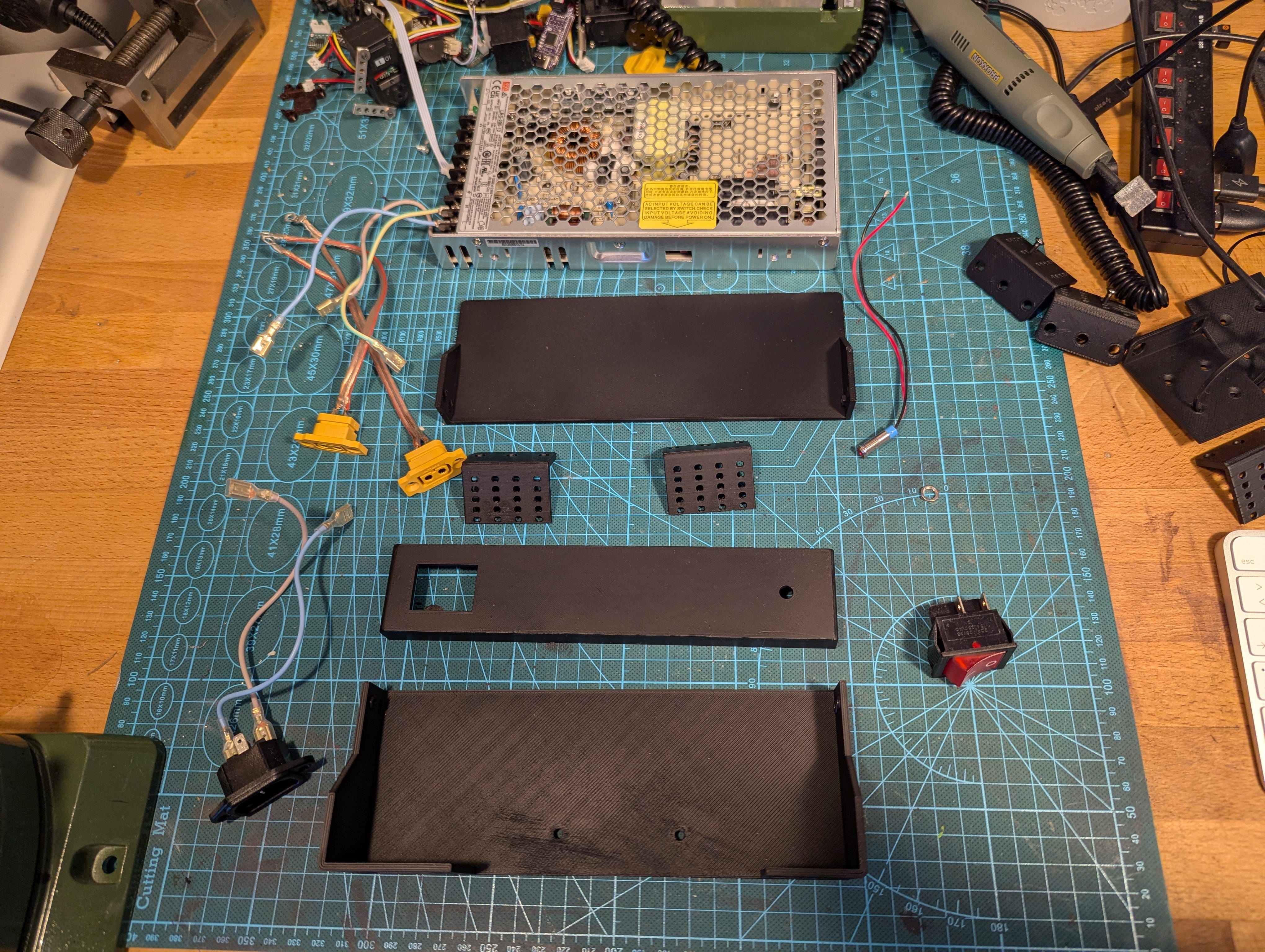
The casing for the power source itself.
I picked black PLA for the print and let it print on Prusa MK3.


The mains connector and XT60 fit in well enough. The bottom screw of XT60 is hard to reach from inside - it’s nearly impossible to hold the nut expected to be there.
I modified the model and added a nut slot here - this way, we can insert the nuts before installation of the connectors.

Why did I omit the nut holes in the top screw for the XT60? because I was not able to put them in a way that would still be easy to 3D print (as you can see on the bottom hole, the hole is quite close to the connector itself).


Wiring itself is pretty simplistic. In case you try to do this on your own, verify this witha certified electrician or somebody responsible before you turn this on.


Overall, I think it looks good. You can notice many scratch marks on the parts. As much as I wanted to just 3D print this and get a free finish, I had to work on the parts a bit. Turns out that this makes the PLA white, so let’s do unplanned spraying with a black can.


Painting was easier than expected, and I think that this will be the preferred way to finish the project anyway, as this way I do not have to stress about modifying the PLA parts during postprocessing.
All is prepared! I call success on the paint, making the parts more pleasant.


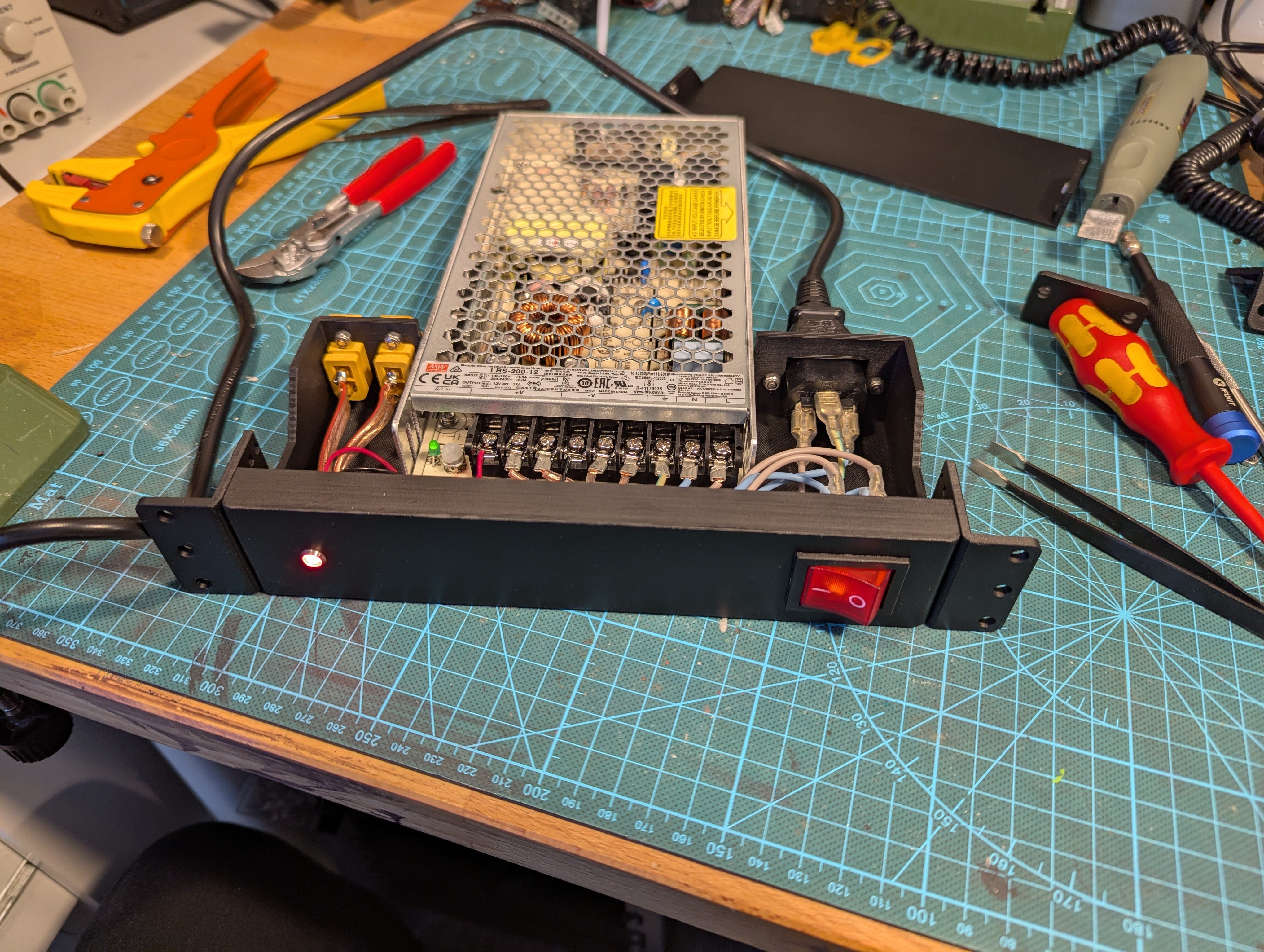


After the painting, I’ve finally got a good feeling about this. The PSU itself looks decent, and as you can see finds itself quite comfortable in the rack.
Note that I picked a different placement position than envisioned. I figured that having an open power source at the bottom for it to collect all the debris is not a great idea.
I will re-print the L-brackets for this, as the screws head sticks out too much. Overall, great success.
PDU
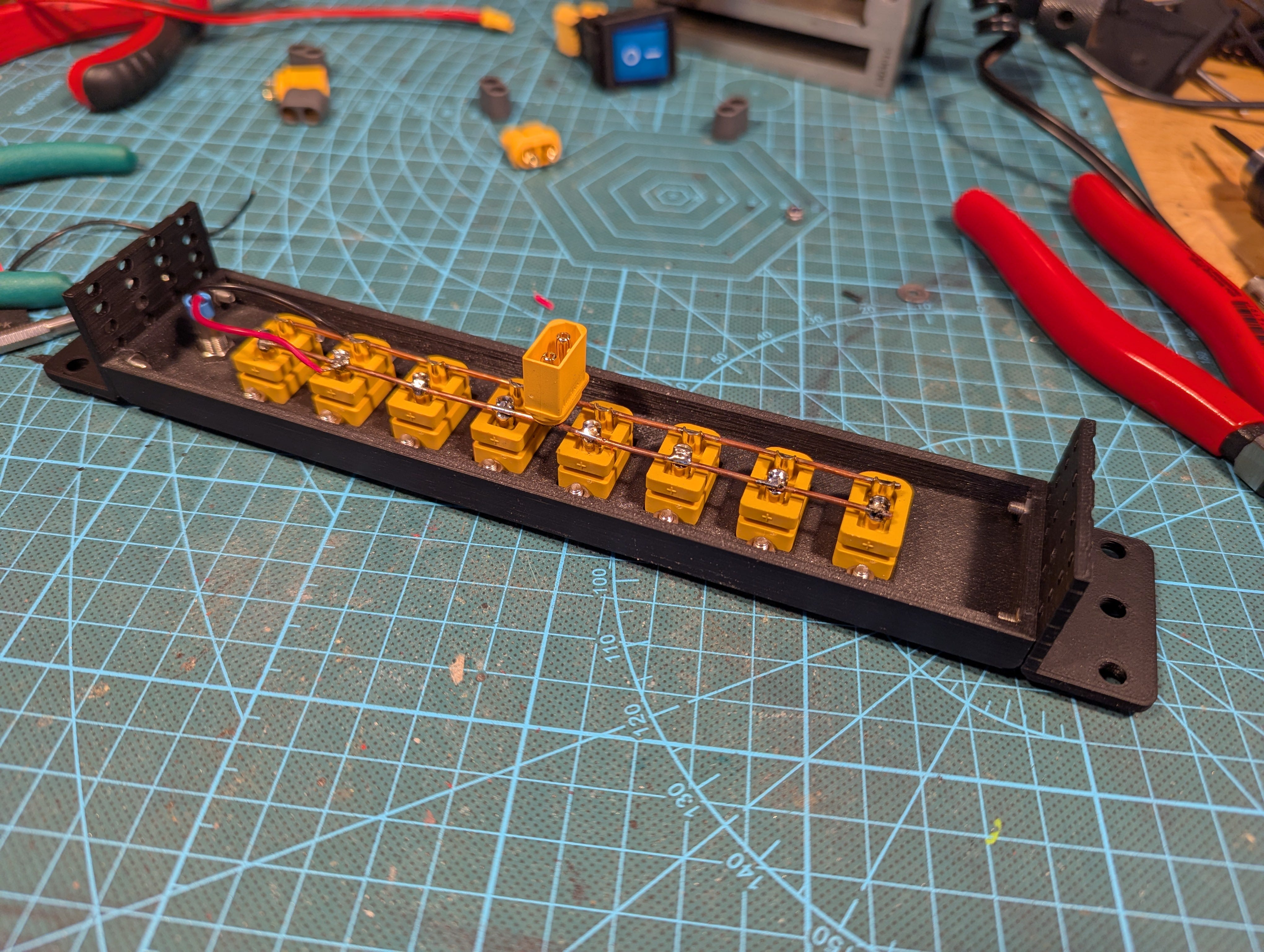
PDU required some manual hand-soldering and creativity with the back-connector for the cable to the PSU.


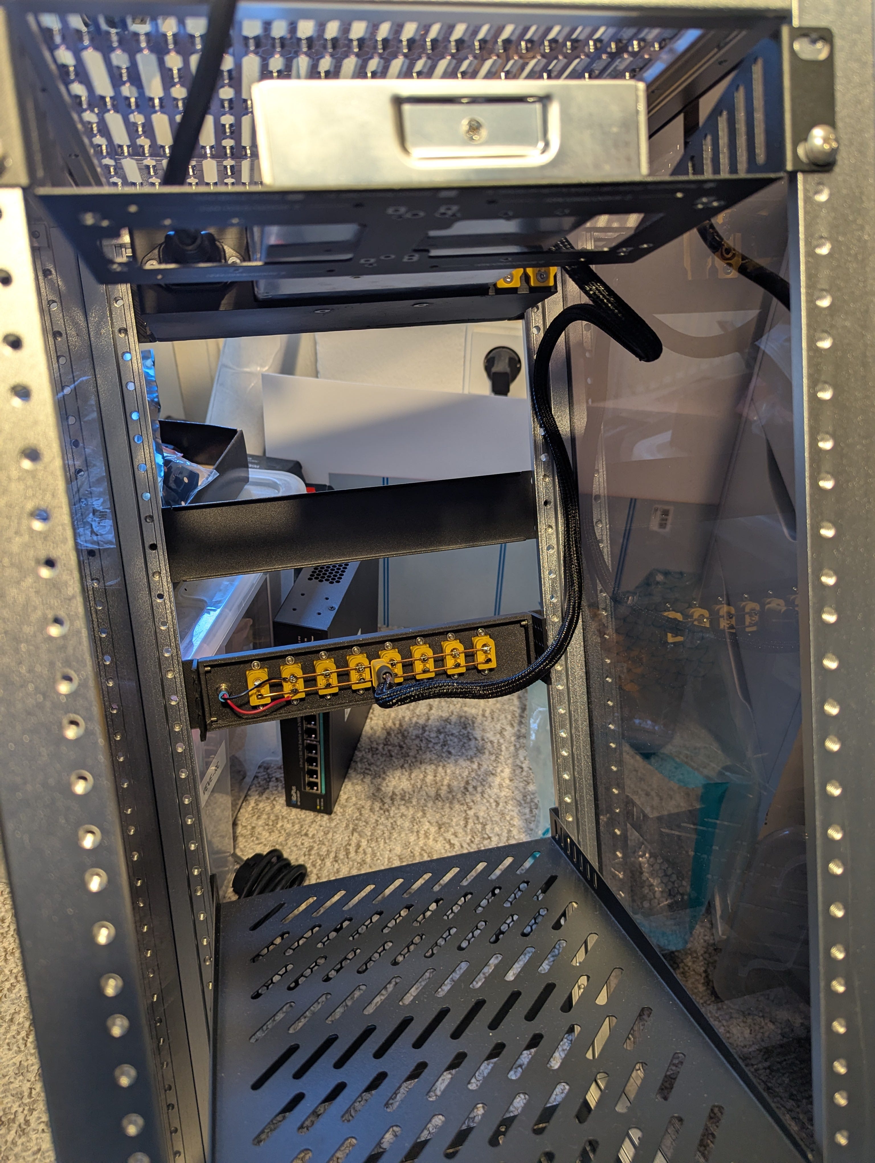
I was aware that I would be leaving open connections in the rack, but it did not bother me during the design phase. After assembling this, I changed my opinion - I don’t feel safe with this, and I modelled a back-cap for the PDU.

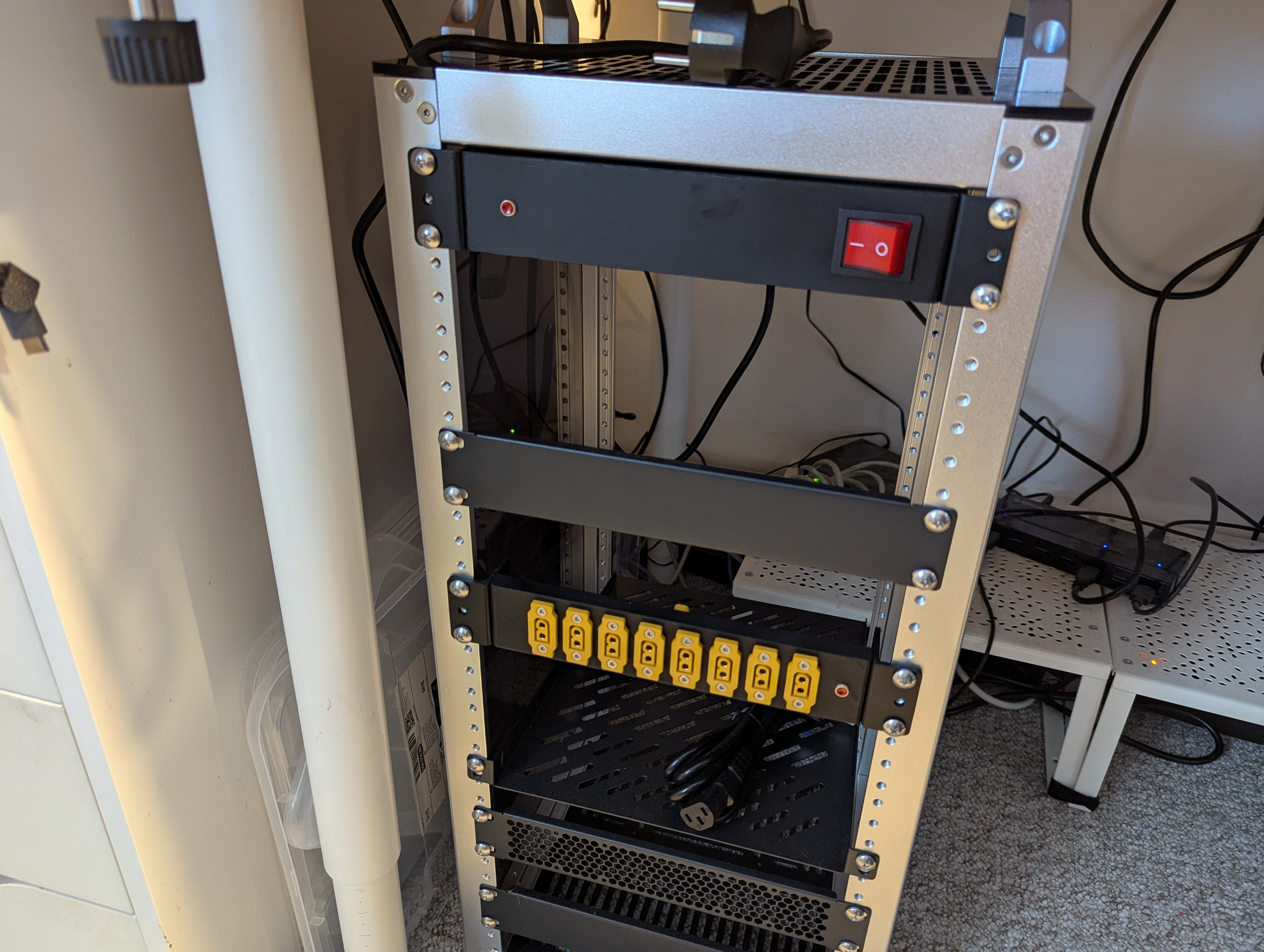
The PDU unit fits in the rack quite well, and this one will be in the expected place.
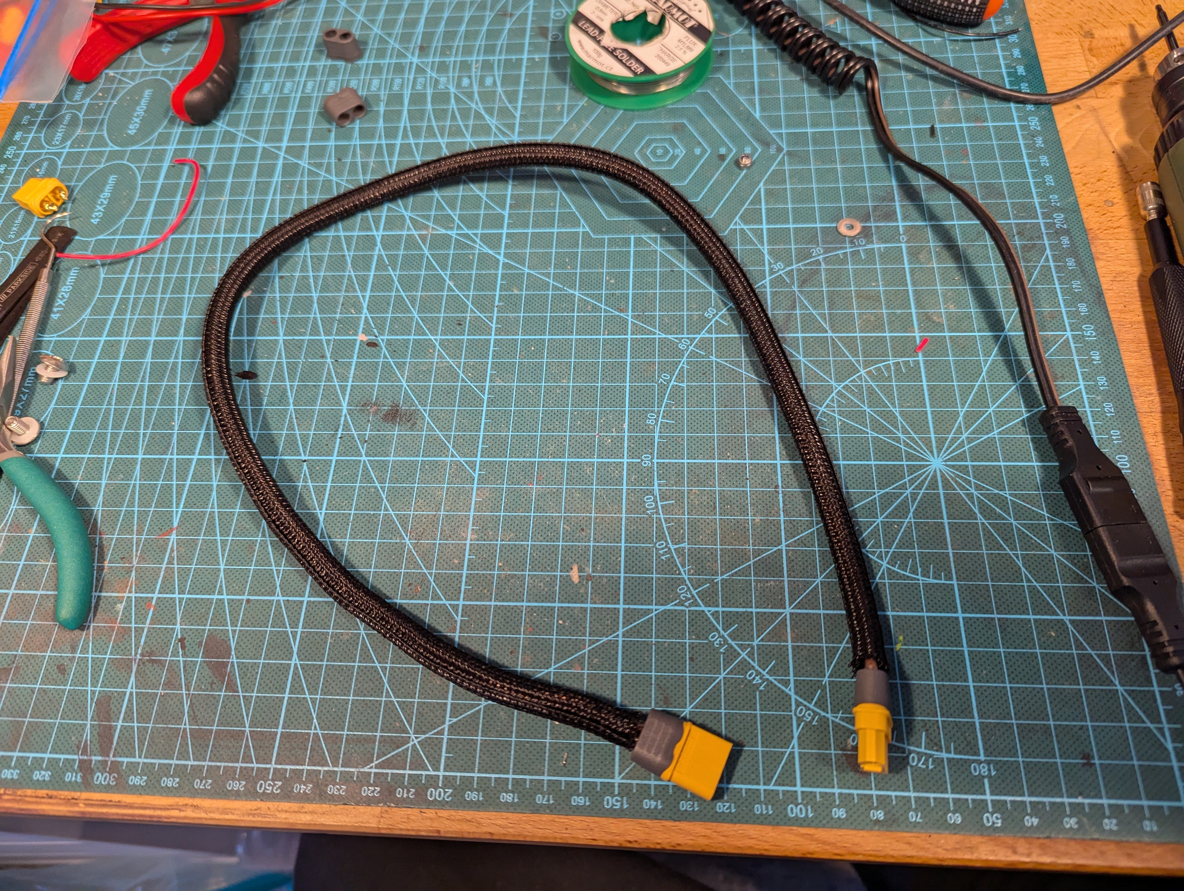
I have bulky custom wiring between the PDU and PSU, which is over-engineered just so I can be sure it won’t get damaged as stuff is inserted in/out.
I lack any guidance for the main wire itself. I will leave this issue for future self to solve, but I think that there will be a simple solution for it.