test_rack: unit

The key component of test_rack is unit - box for one device under test. Let’s build one!
I iterated over two prototypes which I ended up using or last few months for my other side-project: https://hackaday.io/project/194236-servio So the final build is just more polished version of these two.


All files for this are in github repository: https://github.com/emsro/test_rack, the perforated boards are from https://totemmaker.net/ set, but the company seems to be inactive, they should not be hard to replace with alternatives.
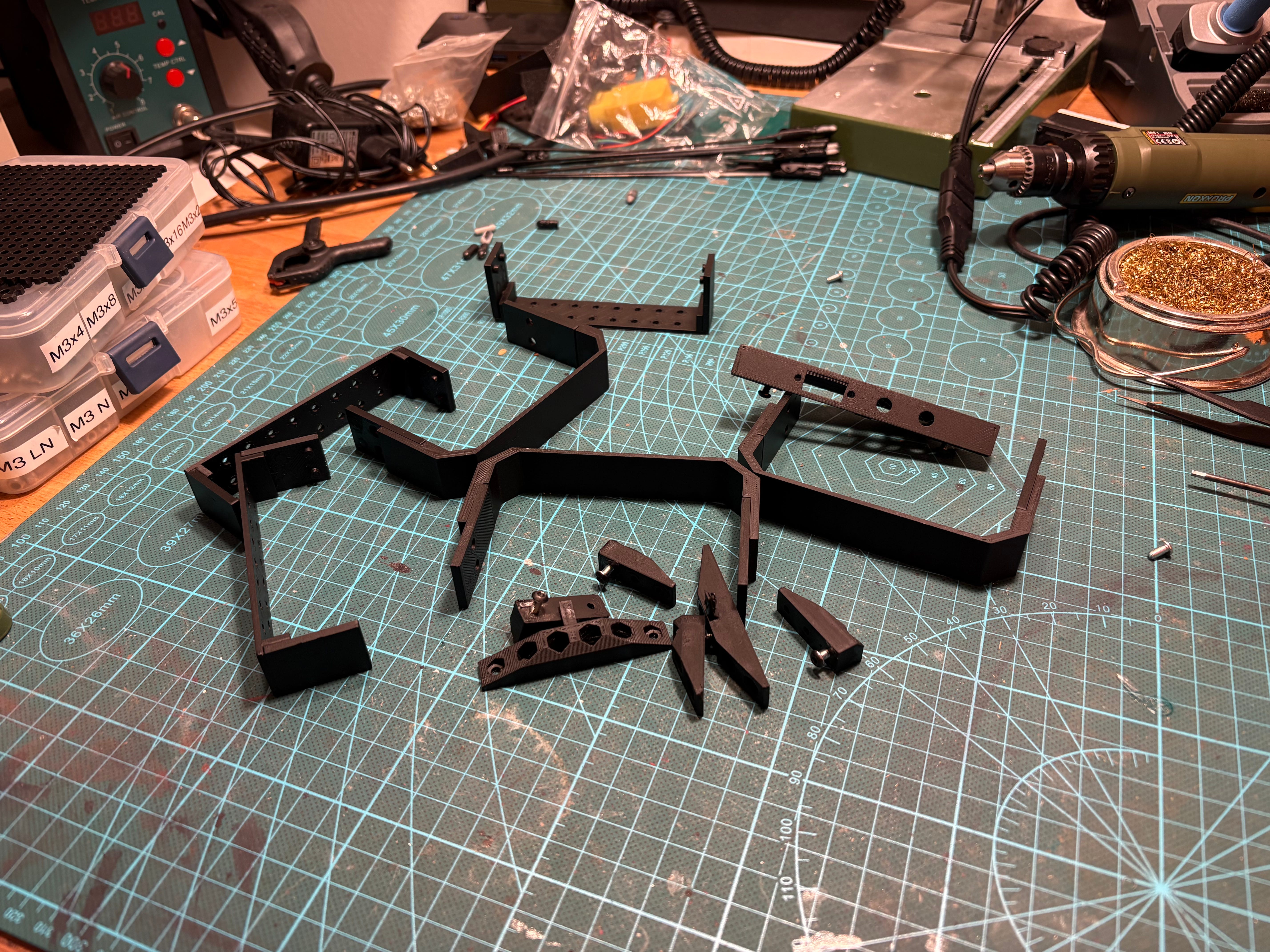
Glue it
With the bunch of parts being printed, the first step is to glue-in 2x4 cylinder magnets.
The three U-gates proved to be invaluable as hand-bar to move the unit around or just to guard it from damage, but at the same time one really wants them gone during work on the unit - they are detachable. To handle that magnets are used to hold them in place.


Given somehow more complicated design I had to resort to multi-part setup and gluing parts together. If I would change something in future versions it would be this.


Both bottom and top part of U-gate has glued-in side-panels with integrated magnets. (Just watch for polarity of magnets to match) After superglue has cured we can test that all fits.
Paint it
Painting the parts was done with my favourite Chaos Black Citadel color. The challenge this time was that it is winter, there was cold outside, will it hold?
To improve my chances (so I don’t have to wait till summer), I found big box and inserted it into the back of my car, did some errands with the car so it heats up and set the internal temperature to highest possible. This proved be effective as it was hot inside the car.
The idea was that the parts, spray can, and air inside the car will get to warm temperature. Then I just stopped at parking lot and quickly sprayed the parts in the back of the car. The enclosure of the box and the car limited air movement so no cold breeze could get in the way.
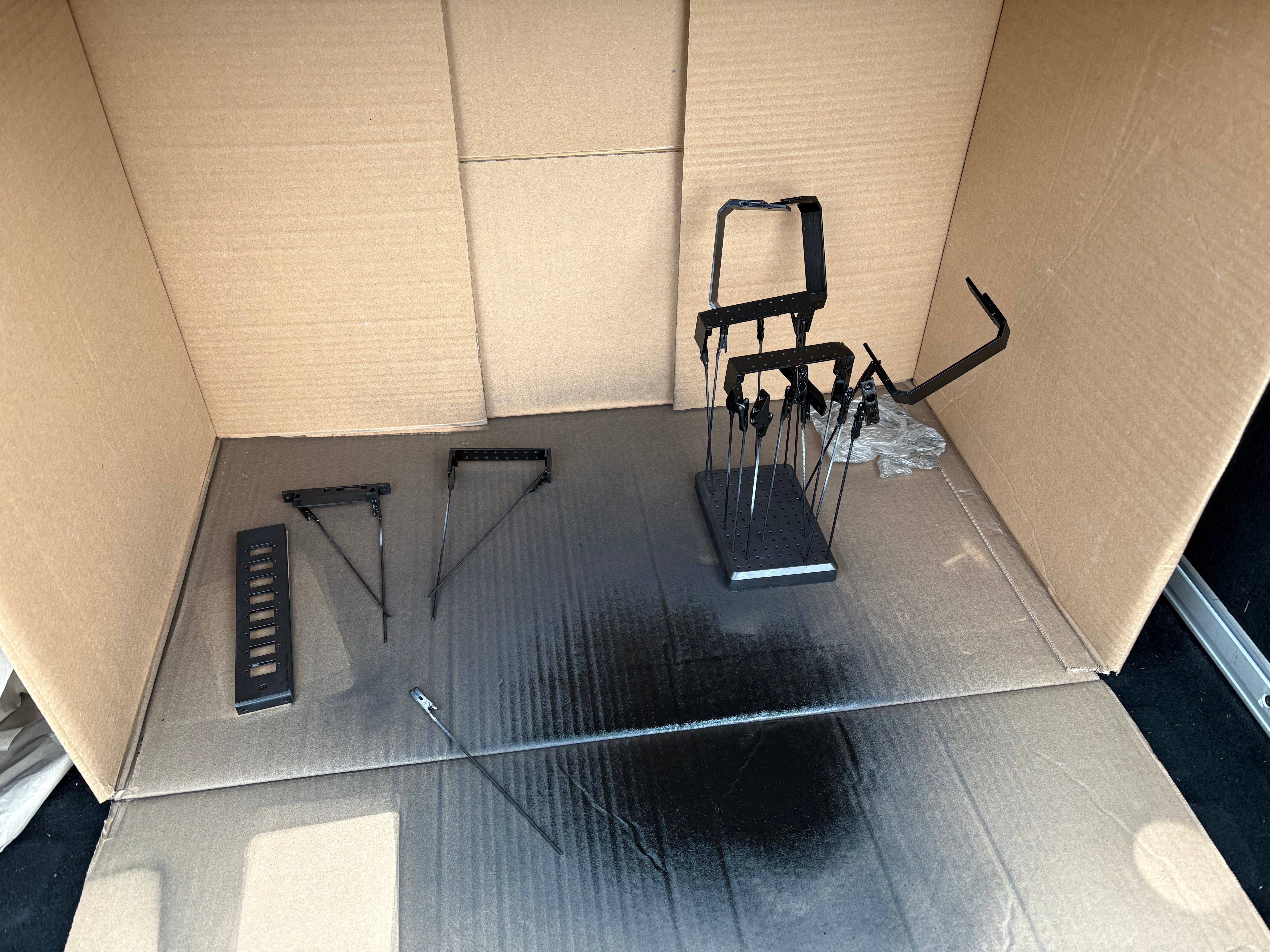
It worked, the color stick well to the parts, even if we were much outside of range that manufacturer recommended at the can. Do this at your own risk!
Assemble it
Assembly starts with the front panel, which contains standard XT60 panel connector, switch and 12V red LED. These were sourced from Amazon.
Note that the switch has a groove in the thread, the provided screw nut has a stump inside to match the groove and protrusion outside. The protrusion will always be aligned in the same direction for any switch - the front panel part has a groove to fit the protrusion so that each switch is aligned the same way - quite handy across multiple units.


The front panel has extrusion that will face bottom of unit to hide the soldering work, this make sit enclosed from three sides - we do not have to worry that much about hiding it. It is screwed together with one totemmaker perforated board (5mm grid of 3mm holes) and bottom side of one U-gate.
I do like the design, it took while to make this front panel so compact that it seems almost non-existing while providing key value: I can see that unit is powered and turn it on/off!


Middle and back U-gate of unit contain no electronics and hence are just few plastic parts screwed together.
I do modify one of the perforated plates to have cut-out holes for wires. In theory they could be passed via the holes but than you would not be able to get them out once connector is soldered on them.


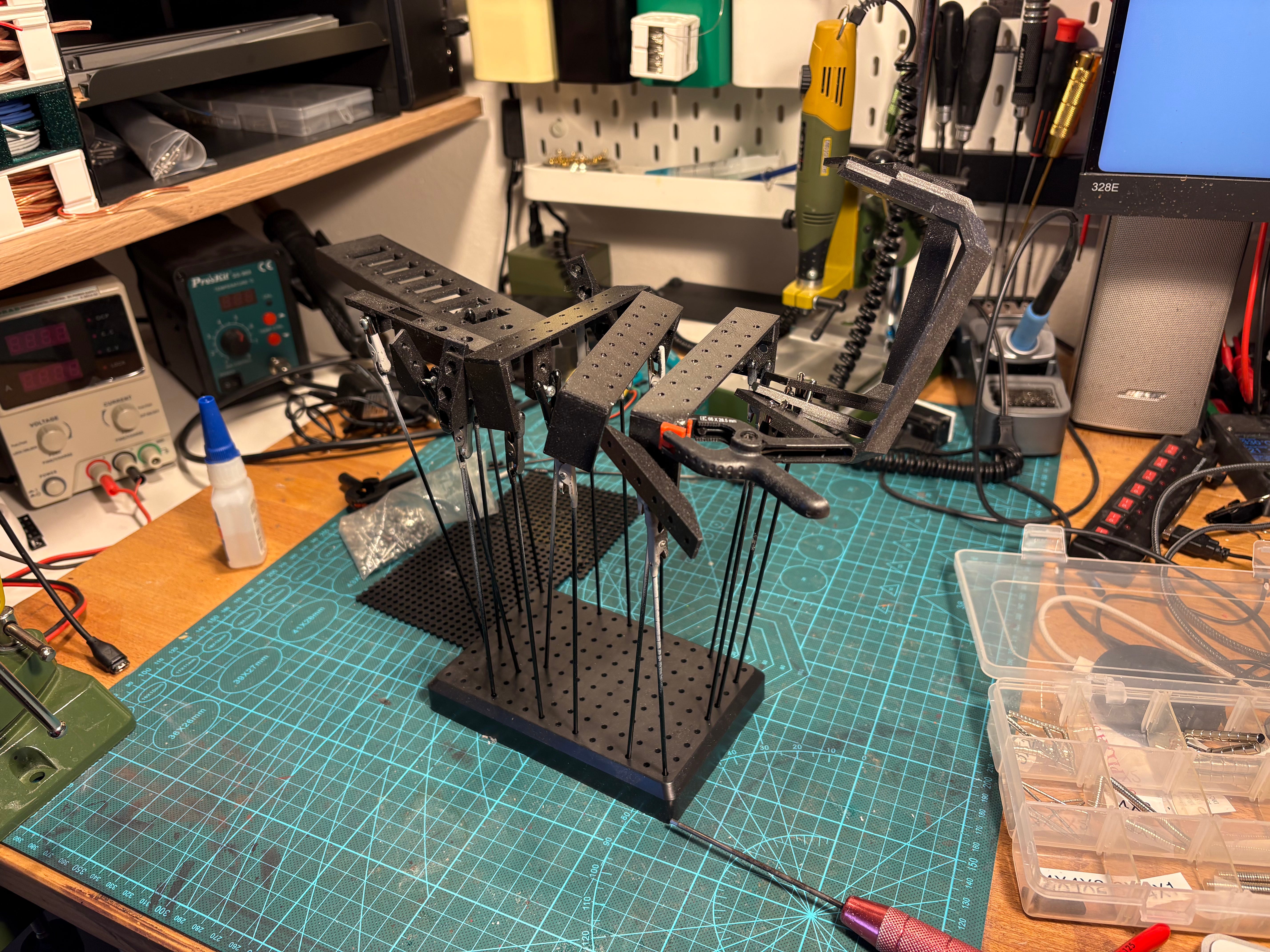
The Unit will be sitting on two rails made out of 10x10 alu profiles (cheap and easy to acquire). As you can see I actually assembled this wrong in previous steps, all that was necessary was just to re-screw it.


This is it, one full unit ready to be put to work.


Use it
Servio is PCB to control DC servomotors, PCB which is quite small. To be able to test it, we need:
Debug board with pogo pins and holder - pogo pins provide access to signals that do not have connector on the board (SWD), and serves as a distribution of existing signals into multiple connectors
DC motor - this unit is used to test dc motors with quadrature encoder, I think that standard yellow motor with hall sensors is enough, it proved tedious to test free spinning motors, so as a form of “load” I like to connect same motor in tandem to slow the main one down
All the wiring
Eventually Raspberry Pi to control this, but so far that is not necessary


All is nicely assembled and it’s ready to use!

